Using PIC16F887 I/O to drive external devices
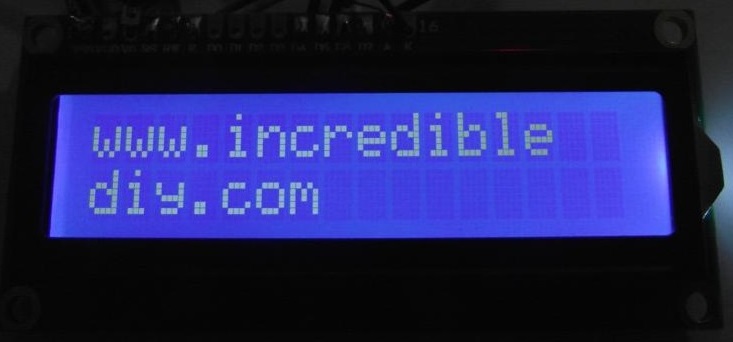
I’ve done a small addition to circuit on the previous circuit.I’m going to use LCD display I added there,to debug my project too.I’m taking out 6 I/O pins from the PIC16F877 via a connector to the breadboard.
Here is the modification to the previous schematic.
I have written a sample code to check the functionality of the I/O pins by setting them to be ‘0’ logic level.The configuration bits are same as for the previous post. Note that the changes are in bold.
| sbit LCD_RS at RB5_bit; sbit LCD_RS_Direction at TRISB5_bit; void main() { Lcd_Cmd(_LCD_CLEAR); |
Here’s how to use the circuit with the breadboard ![]()


Comments